Industry news|2022-05-24| admin
Gear is a kind of mechanical parts that mesh with each other. It has a wide range of applications in mechanical transmission and the entire field. The center distance of the gear is the distance between the centers of two intermeshing gears, which is called the center distance. In some mechanical designs, the center of the gear will be involved. The calculation of the distance between the rack and pinion is often used in mechanical transmission. Today, I will introduce the calculation method of the center distance of the rack and pinion.
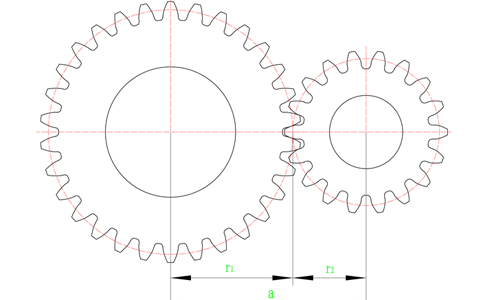
When two gears mesh, it can be considered that the pitch circles of the two gears are tangent. If the two gears are standard gears and there is no error during installation, it can be considered that the pitch circle and the index circle coincide, so when calculating the meshing of the gears It is only necessary to calculate the indexing circle radius of the two gears separately.

As shown in the figure above, r1 and r2 are the index circle radii of the gears, the center distance between the two gears is a=r1+r2, and the calculation formula of the gear index circle radius is: r=m×z÷2, where m is the gear The modulus of , z is the number of teeth of the gear. The modules of the two gears in the above figure are both 2, and the number of teeth is 30 and 18 respectively, so the radii of the index circle are 30 and 18 respectively, and the center distance a is the sum of the two and equals 48.
The above is the calculation method of the center distance when the spur gear meshes. If two helical gears are meshed, the result needs to be divided by the cosine of the helical gear helix angle. For example, the helix angle of the helical gear is 19°31′42″ , you need to divide the calculated center distance by cos19°31′42″ to get the center distance of the helical gear.

The formula for calculating the center distance of the rack and pinion:
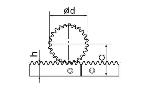
a=h+d/2
h represents the height of the index line, we take the rack of STRRONSE module 2 as an example:
Rack height x rack width=24mm x 24mm
Graduation line height=24mm-2mm=22
2 is the module of the rack, 22 is the height of the index line to the bottom of the rack, the diameter of the straight tooth indexing circle = the number of teeth x the modulus, such as M2 Z20, the diameter of the indexing circle is d=2 x 20=40, 40/2 =20, the center distance is 22+20=42.
In product selection, selecting the appropriate rack and pinion is the key point of mechanical transmission. We provide a complete product portfolio. According to the requirements of the design, we can choose suitable gears for applications such as smooth operation, positioning accuracy, feed force, and installation convenience. Racks, we have a selection of economical and precision series of linear systems, parameters that perfectly match your system, such as the maximum torque that the rack and pinion can withstand and the meshing clearance of the rack and pinion, etc.
When we design the running structure of the rack and pinion, the center distance is a very important parameter, which needs to be adjusted by the engineer in the later stage according to the actual situation to achieve the required accuracy or other requirements, and a margin should be left in the design and installation.
